Parts
I ordered my first set of parts from Amazon, here’s what I got:
- Raspberry Pi 3 Model B Motherboard ($40)
- 5pcs DS18B20 Temperature Sensors ($12)
- 5V 2.5A Power Supply ($10)
- Electronics Starter Kit with Breadboard ($13)
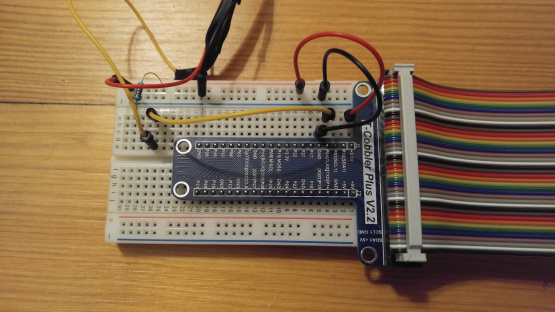
- GPIO T-Cobbler with Ribbon Cable ($10)
- A 16GB MicroSD card that I had lying around
To be fair, I didn’t do a whole lot of research before buying these parts, and probably could have found some of them cheaper elsewhere. The parts that came with the Elegoo kit were okay, but I am mostly just using the cables and breadboard. The breadboard is fairly small, which made working with the cobbler a little difficult. I ended up connecting the Pi directly to the breadboard without the cobbler, and have ordered a large breadboard as well.
Getting the Pi up and running
- I downloaded Raspian Jesse Lite
- I followed these instructions to write the image to my SD card
- I plugged the Pi into my TV via HDMI, and my keyboard and mouse into the Pi’s USB ports (my computer monitors don’t have HDMI ports)
- I ran raspi-config to setup the keyboard layout and timezone. I also was able to enable SSH from this menu. (Go to that link and Ctrl-F for more detailed instructions.)
- I followed these instructions to set up the WiFi connection.
- Finally, I moved my Pi and all the electronics stuff I bought over to my desk.
Setting up for development
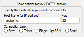
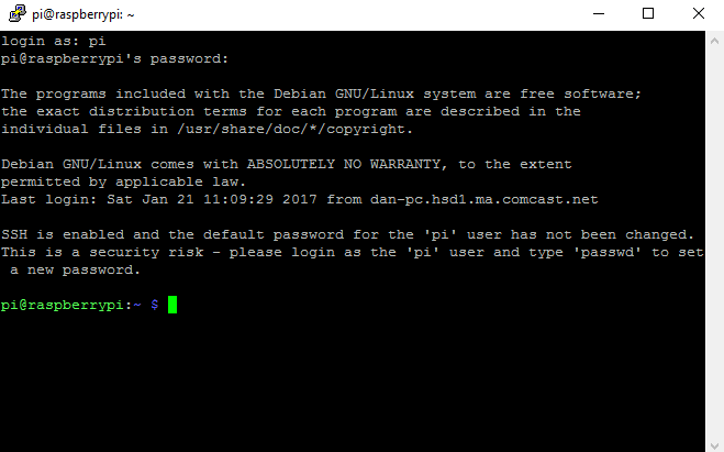
I used PuTTY to connect to the Pi from my PC (The default username/password is pi/raspberry).
And, voila!
Schematics
Now that the Pi was configured, I was ready to set up the temperature sensors.
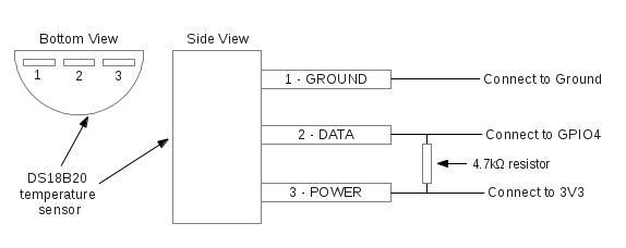
I found this site very useful for getting started with the sensor, and learning how to read it from the Pi. The schematic they provided was simple, and I followed the instructions from step 2 and 3 to get it working at first.
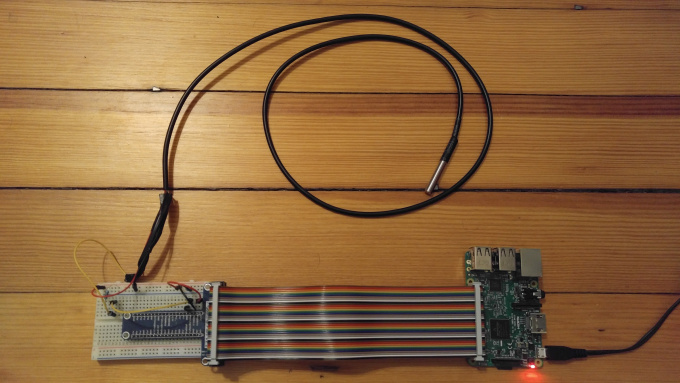
I was able to plug the sensor into the breadboard without any modification to the sensor’s wires, but I found that they fell out of the breadboard pretty easily. I figured that I was going to go through a lot of trial and error (I was right), so I decided to splice the ends of the sensor with the cables from the electronics kit to make the connections a little stronger.
The schematics call for a 4.7k Ohm resistor. The closest resistor in the kit I bought was a 5k Ohm resistor. I did a little googling, and it seemed like it should still work. So, I plugged everything in, according to the schematic above. This is the configuration that I got working, after a little trial and error:
Reading the Temperature
Following the instructions from the schematics site above, I typed these commands into the terminal:
sudo modprobe w1-gpio
sudo modprobe w1-therm
cd /sys/bus/w1/devices/
At first, I saw a folder that looked like ‘00-0000…’. This happens when the sensor is not wired correctly. I went back to the breadboard (after turning off the Pi) and was a bit more careful when following the schematics. I think that I misplaced the resistor initially.
In any case, once I turned it back on, I reran the above commands, and saw that my sensor’s serial number appears in the …/devices/ folder!
I was then able to read the sensor like so:

The temperature “t=20187” means that it is 20.187 degrees Celsius in my living room.
Next time I’ll figure out a way to log the data.
-Dan